

KKS Antenna is an equipment included in the global positioning system developed for İMECE Satellite. It provides:
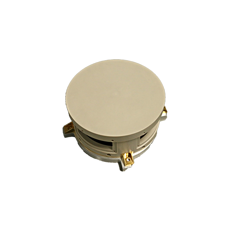
KKS Antenna equipment is included as 2 pieces in the Global Positioning System equipment developed for the IMECE Satellite. The operating frequency band range is 1100-1600 MHz. It offers >7 dBiC gain at right-angle viewing angles. It is designed with circular polarization and has a protective radome.
Mass 0.490 kg
Size: 163 mm x 163 mm x 69 mm (Width x Length x Height)
RF
İMECE, AYAP-1
Thermal: -20°C to +50°C
Vibration
Shock
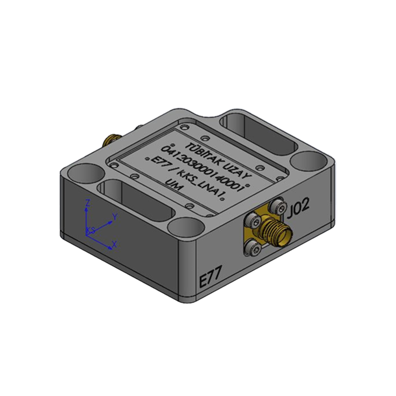
KKS LNA is an equipment within the global positioning system developed for İMECE Satellite. It provides:
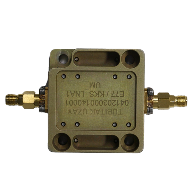
Mass 0.082 kg
Supply: 5V
Power: 0.6 W (nom)
Size: 60 mm x 52 mm x 20 mm (Width x Length x Height)
RF, DC
İMECE, AYAP-1
Thermal: -20°C to +50°C
Vibration
Shock
MIL-STD-461F EMC
KKS RF GDB is an equipment within the global positioning system developed on the İMECE Satellite. It provides:
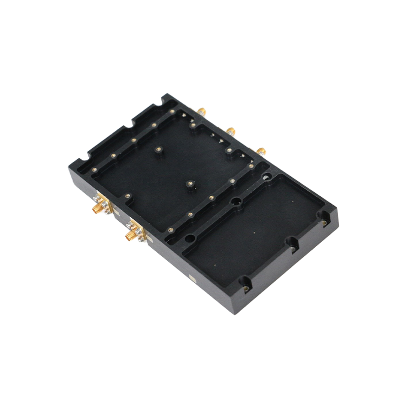
The GPS RF GDB equipment is included in the global positioning system equipment developed for the İMECE Satellite. It is located between GPS LNAs and GPS Electronic Unit equipment. It receives the DC supply voltage from the GPS Electronic Unit equipment, feeds itself and feeds the GPS LNA, which will receive the signal from the GPS Antenna. It divides this signal power into 3 equal parts and transmits it to the GPS Electronic Unit equipment that comes after it. It has a built-in DC voltage regulator. It has 100kRad resistant RF switch and is compatible with 50 ohm system in input and output ports.
Mass x.xx kg
Supply: 5V
Power: 0.25 W (nom)
Size: XX mm x YY mm x ZZ mm (Width x Length x Height)
RF, DC
İMECE, AYAP-1
Thermal: -20°C to +50°C
Vibration
Shock
MIL-STD-461F EMC
The S-Band Transponder is being developed for deep-space missions which will be used for telemetry/telecommand communications and ranging . The modular design of the S-Band Transponder allows it to be tailored to the needs of various space platforms.
The S-Band Transponder Equipment provides the following features to the satellite flight segment:
Supply: 28V nominal (16V - 40V Input voltage range )
Power Consumption: <30W@25C (When both receiver and transmitter are active)
Size: 304 mm x 216 mm x 96 mm (W x L x H)
Mass 4 kg
Control: CAN
Data RS-422
RF: SMA, 50 Ohm
AYAP-1
Thermal:-20°C to +50°C
Vibration
Shock
EMI/EMC: MIL-STD-461F
Lifetime: 3 years
The S-Band Transceiver Equipment is a communication equipment for low-altitude satellites that provides command/spacemetry communication between the satellite and the ground. Its main task is to perform uplink/downlink communication physical layer functions and to provide command and measurement functions within the on-board satellite operation. Thanks to its modular equipment structure, the S-Band Transceiver Equipment can be adapted to different space platform requirements.
The S-Band Transceiver Equipment provides the following features to the satellite flight segment:
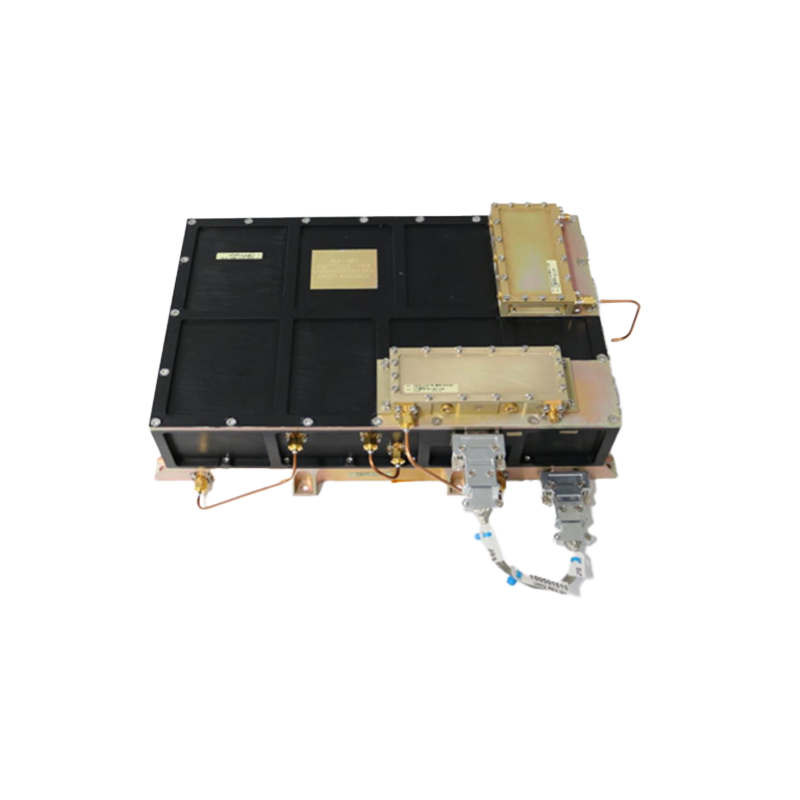
Supply: 28V nominal (16V - 40V Input voltage range)
Power Consumption: <30W@25C (When both receiver and transmitter are active)
Size: 304 mm x 216 mm x 96 mm (W x L x H)
Mass 4 kg
Control: CAN
Data RS-422
RF: SMA, 50 Ohm
İMECE
Thermal: -20 to +50 C
Vibration
Shock
EMI/EMC: MIL-STD-461
Lifetime: 7 years
The S-Band Receiving Patch Antenna is an equipment used in S-Band communication on İMECE Satellite. It features:
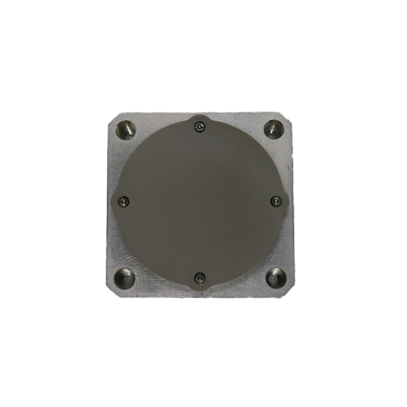
Mass 0.177 kg
Dimensions: 92 mm x 92 mm x 27 mm (W x L x H)
RF
İMECE, AYAP-1
Thermal: -50°C to +100°C
Vibration
Shock
The S-Band Receiver Redundancy Ring is the configuration part located between the S-Band Receiver Patch Antennas and the S-Band Receiver Unit on the İMECE Satellite. It provides:
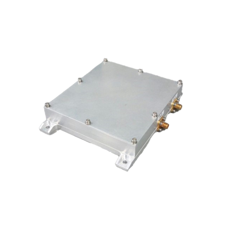
The S-Band Receiver Redundancy Ring is a completely passive configuration element located between the S-Band Receiver Patch Antennas and the S-Band Receiver Unit on the IMECE Satellite. The function of the S-Band Receiver Redundancy Ring is to send the RF signal from the ground station, received by the S-Band Receiver Patch Antennas, to the S-Band Receiver Unit. The S-Band Receiver Redundancy Ring equipment has RF connections with the S-Band Receiver Unit and the S-Band Receiver Patch Antennas. The operating center frequency of the S-Band Receiver Redundancy Ring is 2061 MHz.
Mass 0.297 kg
Size: 131 mm x 146 mm x 27 mm (W x L x H)
RF
İMECE, AYAP-1
Thermal: -20°C to +50°C
Vibration
Shock
The S-Band Transmitting QFH Antenna is an equipment used in the S-Band communication on İMECE Satellite. It features:
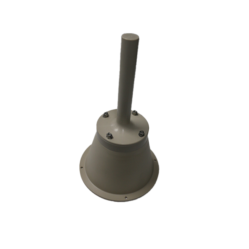
Mass 0.348 kg
Size: 149 mm x 149 mm x 253 mm (W x L x H)
RF
İMECE, AYAP-1
Thermal -50°C to +100°C
Vibration
Shock
The S-Band Transmitting Patch Antenna is an equipment used in S-Band communication on İMECE Satellite. It features:
Mass 0.168 kg
Dimensions: 92 mm x 92 mm x 27 mm (W x L x H)
RF
İMECE, AYAP-1
Thermal: -50°C to +100°C
Vibration
Shock
The S-Band Transmitter Redundancy Ring is the configuration part located between the S-Band Transmitter Patch Antenna, the S-Band Transmitter QFH Antenna, and the S-Band Transmitter unit on the İMECE Satellite. It provides:
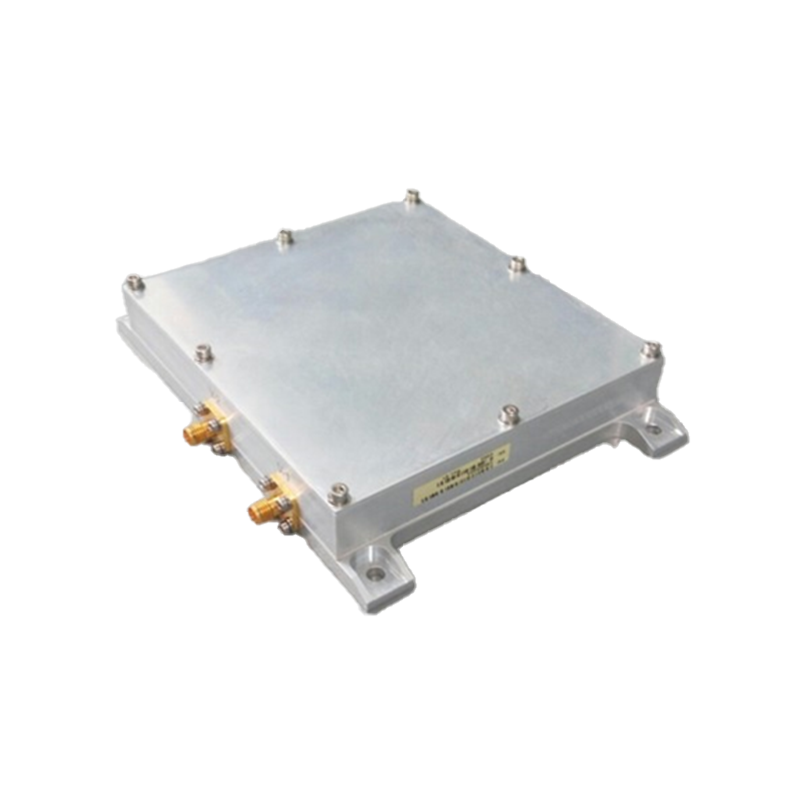
- The S-Band Transmitter Redundancy Ring is a configuration part consisting of completely passive elements located between the S-Band Transmitter Patch Antenna, S-Band Transmitter QFH Antenna and S-Band Transmitter Unit on the IMECE Satellite.
- The role of the S-Band Transmitter Redundancy Ring is to ensure that the power of the RF signal from the S-Band Transmitter Unit is divided between the S-Band Transmitter Patch Antenna and the S-Band Transmitter QFH Antenna in certain proportions.
- The S-Band Transmitter Redundancy Ring equipment has RF connections with the S-Band Transmitter Unit, S-Band Transmitter Patch Antenna and S-Band Transmitter QFH Antenna.
- The S-Band Transmitter Redundancy Ring operating frequency range is 2200 MHz to 2290 MHz.
Mass 0.293 kg
Size: 131 mm x 146 mm x 27 mm (W x L x H)
RF
İMECE, AYAP-1
Thermal: -20°C to +50°C
Vibration
Shock
The X-Band Transmitter is a high data rate communication equipment developed for deep-space missions. Its task is to transmit payload data from the satellite to the earth. The modular design of the X-Band Transmitter allows it to be tailored to the needs of various space platforms.
The X-Band Transmitter Equipment provides the following features to the satellite flight segment:
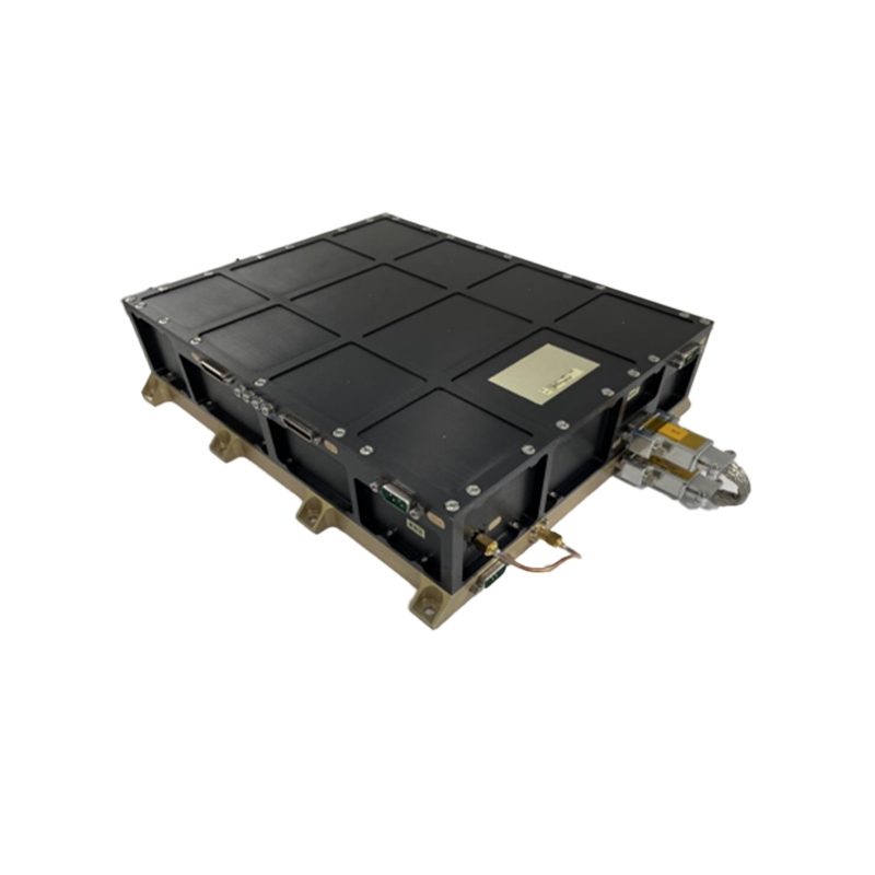
Supply: 28V nominal (20V - 36V input voltage range)
Power Consumption: <65W@25C
Dimensions: 290 mm x 260 mm x 80 mm (W x L x H)
Mass 4 kg
Control: CAN
Data: LVDS
RF: SMA, 50 Ohm
AYAP-1
Thermal:-20°C to +50°C
Vibration
Shock
EMI/EMC: MIL-STD-461F
Lifetime: 5 years
The X-Band Transmitter is a high data rate communication equipment developed for low-earth orbit satellites. Its task is to transmit payload data from the satellite to the earth station at high data rate. The modular design of the X-Band Transmitter allows it to be tailored to the needs of various space platforms.
The X-Band Transmitter Equipment provides the following features to the satellite flight segment:
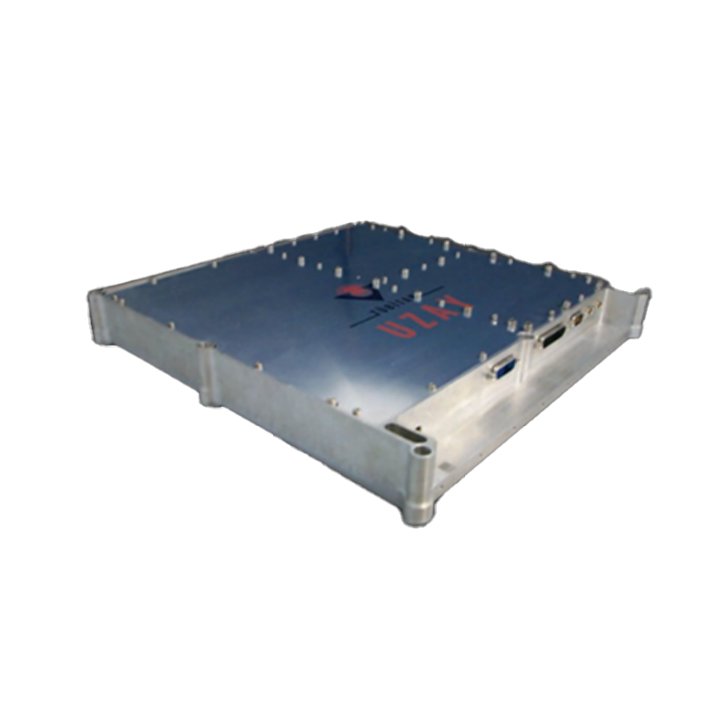
Supply: 28V nominal (20V - 36V input voltage range)
Power Consumption: <65W@25C
Dimensions: 290 mm x 260 mm x 80 mm (W x L x H)
Mass 4 kg
Control: CAN
Data: Spacewire
RF: SMA, 50 Ohm
RASAT, GÖKTURK-2, İMECE
Thermal: -20°C to +50°C
Vibration
Shock
EMI/EMC: MIL-STD-461
Lifetime: 7 years
The X-Band Transmitter is a high data rate communication equipment developed for low-earth orbit satellites. Its task is to transmit payload data from the satellite to the earth station at high data rate. The modular design of the X-Band Transmitter allows it to be tailored to the needs of various space platforms.
The X-Band Transmitter Equipment provides the following features to the satellite flight segment:
Supply: 28V nominal (16V - 40V Input voltage range)
Power Consumption: <56W (-20°C to +50°C)
Dimensions: 290 mm x 260 mm x 80 mm (W x L x H)
Mass 4.06kg
Control: CAN, MIL-STD1553B
Data: LVDS
RF: SMA, 50 Ohm
İMECE
Thermal: -20°C to +50°C
Vibration
Shock
EMI/EMC: MIL-STD-461F
Lifetime: 7 years
The Electromechanical Steerable Antenna (ESA) is a production of the interdisciplinary cutting-edge technologies and engineering. It provides:
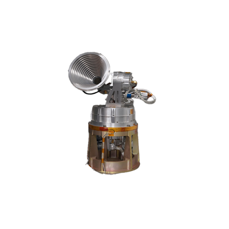
Supply: 28V unregulated
Power: 6.15W (nom), 8.3W (max)
Mass: 5 kg, ±%5 (including antenna)
Dimension (Mechanism): 192 mm x 292 mm x 440 mm (W x L x H)
Dimension (Drive Module): 165 mm x 257 mm x 58 mm (W x L x H)
RS-422
CAN
İMECE
Thermal: -20°C to +50°C
Vibration
Shock
EMI/EMC: MIL-STD-461
Lifetime: +5 years (more than 21,000 total cycles)
TXTX Antenna is developed for X-band transmiting system for İMECE Satellite. It provides:
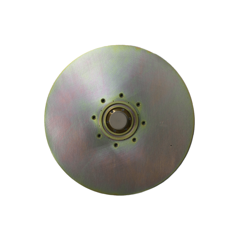
TXTX Antenna is a medium-gain product that supports the X-Band Transmitter System developed for the IMECE Satellite. The operating frequency band range is 8000-8400 MHz. It has a gain of 4-7 dBiC at specified elevation angles. It is designed with circular polarization (LHCP or RHCP) and has a protective radome.
Mass 0.11 kg
Dimensions: 172 mm x 172 mm x 29 mm (W x L x H)
RF
İMECE, AYAP-1
Thermal: -50°C to +100°C
Vibration
Shock