
UZAY
Orbit and Orientation Control Subsystem
Star Traces
The Star Tracks equipment is a robust and modular opto-electronic sensor compatible with different space orbits. Thanks to its modular structure, it can meet the orientation determination needs of different Heading and Trajectory Control Systems (GCS).
Star Traces Features
Main Features
- 1 electronic unit can be connected to up to 3 optical units via the fast SpaceWire interface
- HAS-2 CMOS APS sensor and thermo-electric cooler
- Electronic unit embedded software capable of processing multi-optical unit data
- Electronic unit embedded software with autonomous orientation acquisition, tracking algorithms and star catalog
- Providing the fused orientation quaternion to the flight computer (when using multiple optical units)
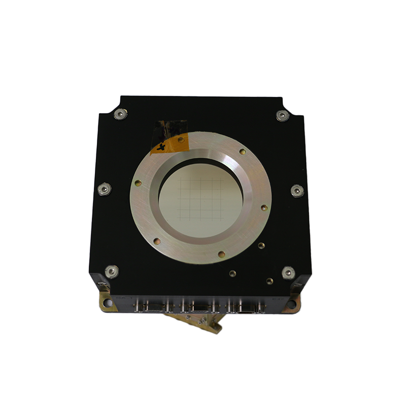
Optical Unit Specifications
Radiation resistant siferic lenses
70 mm focal length, f/1.4
15 x 15 degree field of view
Light curtain protecting the sensor from unwanted light (from the Sun and Earth)
Radiation tolerant HAS-2 APS CMOS sensor, 1,024 x 1,024 pixels sensor resolution
Optical Unit Budgets
Supply: Power supply is provided through the electronic unit.
Power Power supply is provided through the electronic unit.
Size: 159 mm x 130 mm x 343mm (Width x Length x Height)
Weight: 3 kg
Electronic Unit Specifications
Dual Core, High Reliability LEON3FT Based Microcontroller
RTEMS Real-Time Operating System
CCSDS and ESCC Compliant TM-TC Interface
Bootloader, Driver and Hardware Support Software Package (BSP), Star Traces Software
8 MB SRAM, 256 MB SDRAM, 2 MB PROM [All Error Correction Coding (ECC) protected]
Electronic Unit Budgets
Supply: 28V nominal (16V - 40V voltage input range)
Power: 20W (nominal)
Size: 308 mm x 279 mm x 148 mm (Width x Length x Height)
Weight: 7.3 kg
Optical Unit Interfaces
3 x 2 SpaceWire
3 x 2 Power and Time Synchronization Interface (RS-422)
Electronic Unit Interfaces
Bus: 2 x 2 CAN
Test Interface : 2 x 1 JTAG
Synchronization : 2 x 2 PPS Input (RS-422)
Power Interface : 2 x 2 Main Power Input
History / Platforms
IMECE, TÜRKSAT 6A
Environmental / Reliability
Thermal:-20 to +50 C
Vibration
Shock
EMI/EMC: MIL-STD-461
Lifespan 5 - 15 years
SEU resistant
Latchup Immune
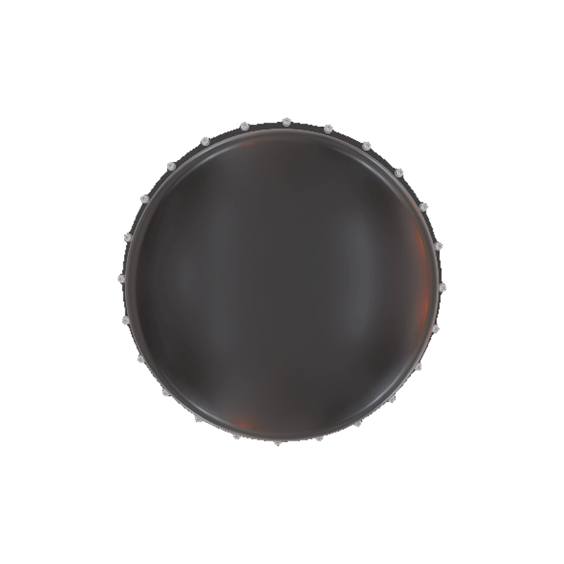
Solar Sensor
The Solar Sensor is a device used in the orientation of satellites by providing data on the direction of the Sun. It is especially critical during the commissioning phase of satellites, in emergency situations and when orientation sensing equipment such as star trackers are not working.
Solar Sensors use analog or digital sensors to generate sun direction data, usually with low accuracy. The developed Solar Sensor is a fully digital, high-performance, high-precision, high-accuracy solution that is robust to critical environmental conditions.
Solar Sensor Features
Main Features
- FPGA-based and radiation-resistant electronic processing unit
- High-resolution and radiation-resistant CMOS sensor
- ±64° two-axis viewing angle
- High-precision solar vector data calculation with 0.1° resolution
- Original optical design and algorithm using extended grating optics
- Solution generation performance with 5 Hz frequency
- Domestically produced optical materials (OPMER)
Hardware Fault Detection, Debugging and Recovery Features
High-reliability electronic processing unit
In-equipment temperature monitoring
Reading in-equipment current and voltage values
Redundant data bus
Algorithm with error detection and correction
Budgets
Supply: 28V (IMECE), 100V (TÜRKSAT 6A)
Power: 3.2 W (IMECE); 3.7 W (TÜRKSAT 6A)
Size: 100 x 100 x 40 mm (IMECE), 124 x 106 x 42 mm (TÜRKSAT 6A)
Weight: 550 g (IMECE), 800 g (TÜRKSAT 6A)
Interface
TM-TC : 2 x CAN ISO (warm redundant)
Pin redundant power interface
History/ Platforms Involved
IMECE, TÜRKSAT 6A
Environmental / Reliability
Thermal:-20 to +50 C
EMI/EMC: MIL-STD-461
Lifespan 5 - 15 years
SEU resistant
Latchup Immune
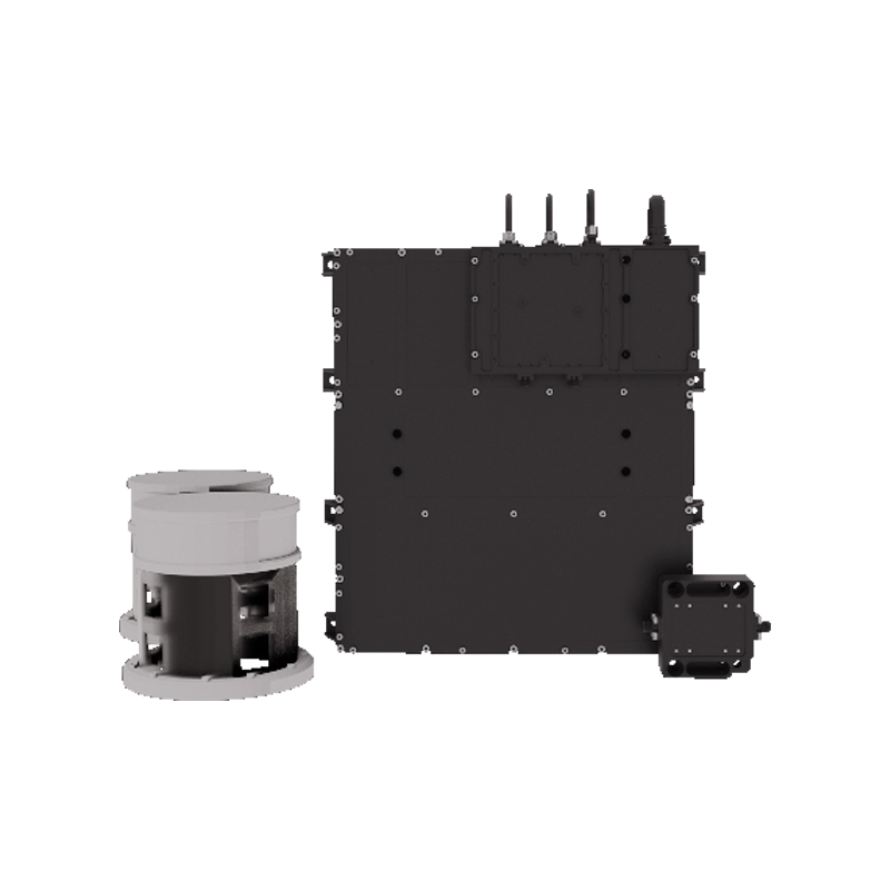
Global Positioning System
KKBS Features
| Parameter | Value |
|---|---|
| Position Accuracy (m, % 90 SEP) | < 10 |
| Speed Accuracy (m/sec, % 90 SEP) | < 0,01 |
| Time Accuracy (April) | < 500 |
| PVT Solution Algorithms | Least Squares, Kalman Filter (Main) |
| Full Convergence After Cold Start | < 1.5 Orbit |
| Possible GNSS Signals |
GPS L1 C/A, L2C, L5 I/Q GALILEO E1 B/C, E5a I/Q |
| Total Number of Channels | 36 |
| Measurement Data from Every Channel | Code Phase, Carrier Phase, Spurious Interval, Doppler, C/N0 |
| Solution Performance Data | GDOP, Number of Satellites |
| Configuration | 2 x Antenna (Ant.), 2 x LNA, 1 x Electronic Unit (EU) |
| Effective Antenna Field of View (°) | 140 |
| Minimum Visible Satellites in LEO | 4 |
| Mass (kg) |
Antenna: 0.5 LNA: 0.1 EU: 3.8 |
| Dimensions (mm) |
Antenna < Φ 165, 70 LNA < 55 x 40 x 20 EU < 300 x 300 x100 |
| Input Voltage (V) | 28 ± 5 |
| Max. Power Consumption (W) | < 15 |
| Data Interface | MIL-STD-1553 |
| PPS Interface | RS422 |
| Other Features | Embedded radiation dosimeter available |
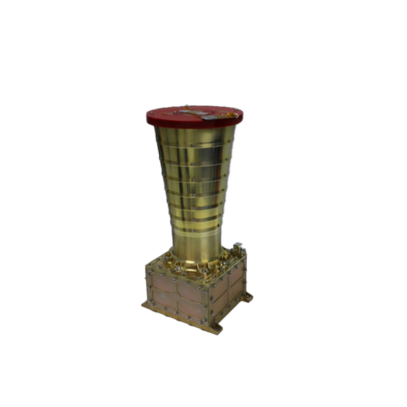
Reaction Wheel
Reaction Wheels are actuators used for the precise control of the orientation of satellites and change or stabilize the satellite's orientation by applying the momentum generated by a high inertia flywheel connected to an electric motor shaft to the satellite. They are the most sensitive orientation element and must operate almost continuously for the entire lifetime of the satellite, so the lifetime of this satellite is highly dependent on the operation of this equipment.
Orientation control and stability in three axes can be achieved by using multiple (usually 4, at least 3) Reaction Wheels.
The Reaction Wheel developed by TÜBİTAK UZAY provides satisfactory performance in terms of momentum storage, torque and wheel speed measurement, zero crossing and micro-vibration features.
Reaction Wheel Specifications
The Reaction Wheel consists of two units, a Mechanical Unit and an Electronic Unit and its most important features are the following:
- Angular momentum value >15Nms,
- Output torque capacity > 200 mNm,
- Total mass 8.5 kg.
Projects
- IMECE : 1 Structural-Thermal Qualification Model, 1 Qualification Model, 1 Flight Model
- TURKSAT 6A : 1 Structural-Thermal Qualification Model, 1 Qualification Test Model, 1 Engineering Model, 1 Flight Model
- AYAP -1 Month Research Program: 1 Structural-thermal Adequacy Model, 1 Adequacy Model, 4 Flight Models
| Features | Unit | Remarks |
|---|---|---|
| Output Torque Capacity | 250 mNm | |
| Angular Momentum Capacity | 15 Nms | @ 4000 rpm |
| Speed range | ± 4000 rpm | |
| Nominal Voltage (LEO) | 28 V | (23 -35 V) |
| Nominal Voltage (GEO) | 100 V | (95-105 V) |
| Interface | CAN | 20 Hz TM/TC interface |
| Mass | 8.5 kg | Total for Wheel Unit and Electronics Drive Unit |
| Protection Features | Overspeed, Over Current, Over/Under Voltage, Over Temperature | |
| Lifespan | 7 years (LEO), 15 years (GEO) | |
| Standby Power Consumption | < 10W | |
| Highest Power Consumption | < 125 W | |
| Operating Temperature | '-20 C / 50 C |