UZAY
Power Systems
PCU
(Power Conditioning Unit)
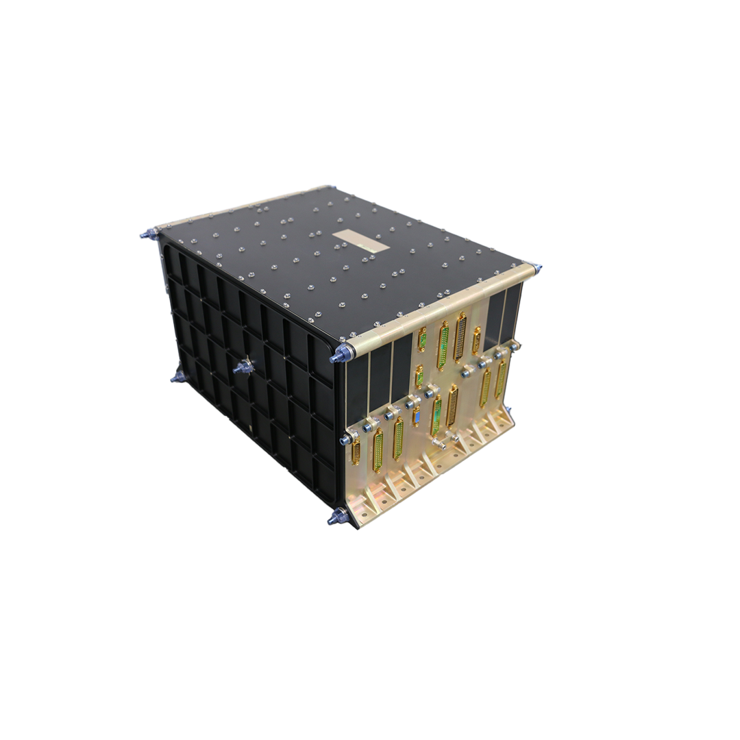
TÜBİTAK UZAY develops and produces Power Conditioning Unit (PCU) to satellite and spacecraft applications for space research missions. PCU is responsible for regulating the main power bus, providing power to the satellite payloads under all possible environmental operation conditions. While regulating the main power bus, PCU utilizes the solar arrays during sunlight and battery during eclipse periods. TÜBİTAK UZAY have been developed 28 V unregulated and 100 V regulated bus power conditioning units for two different satellite projects which are qualified to MIL and ECSS standards. Due to the modular structures, the 100 V regulated bus PCU could be modified up to 9 kW and 28 V PCU could be modified up to 2.4 kW power capability. The design of the PCU is managed to prevent any possible single point failure and hot-cold redundancy is applied to all critical parts of the equipments. The PCU have been qualified under all functional and environmental tests for both İMECE and TÜRKSAT 6A Satellites; both equipments gained space qualifications after the launch of the satellites.
PCU 28V - iMECE
Power Conditioning Unit 28V
Power Conditioning Unit 28V (PCU 28V) is a single integrated and modular unit to power your satellite up to 2.4 kW. The PCU has been developed in the frame of IMECE Satellite Project. The main purpose of the equipment is providing power to unregulated bus (28 ± 5 V) of satellite. PCU can achieve two modes of operation which are battery charging and end of charge. The battery charging operation uses maximum power point traction (MPPT) to utilize solar panel’s power. The internal architecture of equipment is designed to comply with the reliability target with a single unit per spacecraft.
Key Features
- Provides a centralized low impedance point for power distribution.
- Combines the solar arrays and battery in a controlled and MPPT based high efficiency manner.
- PCU can be directly plugged to solar panels and the battery from one side and payload & platform from the other side, without any additional interface.
- Achieves battery charge and end of charge modes under all spacecraft operation conditions.
- Provide to the OBC the battery TM (voltage, current, temperature) necessary for charge management.
- Provide telemetry and telecommunications related to equipment management.
Budget
Mass: 20 ±0.5 kg @ 2.4 kW
Volume: 368 x 428 x 240 mm3 @ 2.4 kW
Power: up to 2.4k W at unregulated 28V bus bar
Interfaces
Unregulated Power Bus, 28± 5V
Battery: Li-Ion
Primary Power Source: Solar Arrays
Data Transfer: CAN Bus
Environmental Conditions
- Thermal: -25°C to +50°C
- Radiation: compatible to LEO ( 5 years mission lifetime)
- EMI/EMC: MIL-STD-461
- Vibrations: 20 g sine, 10 grms in Z plane and 7grms in X-Y plane random
- Shock: 40 to 1,200 g (0.1 to 10 kHz)
Design Details of PCU 28V
The Power Conditioning Unit contains four Battery Charge Regulators (BCR) which are designed to utilize Solar Array Power by using MPPT. Each BCR can transfer 600W power to Battery/Bus bar. The PCU also has Auxiliary Power Supply (APS), Data Interface Unit and bank of capacitors to maintain its operation. There is also an optional unit named Experimental Panel Interface (EBPI) which gives you an opportunity to provide heritage any experimental solar arrays up to 100W.
Performance
- Power Output: Up to 2.4kW under unregulated 28V
- Bus Voltage: 28 ±5 V unregulated
- Efficiency : 94% (Full Load of Operation)
- Battery type: Li-Ion
- Battery charge current: 18 A (maximum)
- Battery charge mode: MPPT & EoC (Constant Voltage)
- Battery Management: Autonomous MPPT based regulation
PCU 100V - TÜRKSAT 6A
Power Conditioning Unit 100V
Power Conditioning Unit 100V (PCU 100V) is designed by TÜBİTAK UZAY for TÜRKSAT 6A Satellite in a fault tolerant and space qualified manner. The main bus regulation is managed by solar array regulators and battery charge regulators during sunlight and by battery discharge regulators when the power generated by sun is not enough to handle satellite's needs. The excessive power generated by solar arrays is stored in two Li-Ion batteries of the satellite. The internal architecture of the equipment is designed to comply with the reliability target with a single unit per spacecraft.
Key Features
- Power Bus Voltage: 100±1V
- Bus Voltage Ripple:
<0.4 Vp-p Sunlight mode (Solar Panel Regulator)
< 0.1 Vp-p Eclipse mode (Battery Discharge Regulator) - Battery Charge Current : 0-10A (40 mA resolution)
- Battery Voltage : 56V – 84V
- Battery Charge Modes : Constant current, constant voltage
- Sunlight Power Capacity : 10 kW
- Discharge Power (Eclipse) :
9 kW (6 Battery discharge regulator operating mode)
7.5 kW (1 Battery discharge regulator fault mode) - Power Conversion Efficiency:
Solar Array Regulators > 98,8 %
Battey Charge Regulators > 93,1 %
Battery Discharge Regulators > 95,9 % - Protections : Overvoltage Protection, Overcurrent Protection, Discharge Power Limitation
Mechanical Features
Mass: 48±0.5 kg
Dimensions: 752 mm x 428 mm x 240 mm (W x H x L)
Interfaces
Bus bar: 100±1 V
Primary Power Source: Solar Arrays
Secondary power source: Li-Ion battery
Data transfer: MIL-STD-1553B and discrete lines
Qualification Requirements
- Thermal: 25°C to +50°C
- Radiation: compatible to GEO ( 15 years mission lifetime)
- EMI/EMC: MIL-STD-461
- Vibration/Shock: ECSS-E-ST-10-03
Use in Power Subsystem Scope
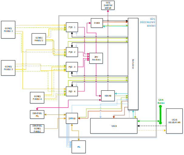
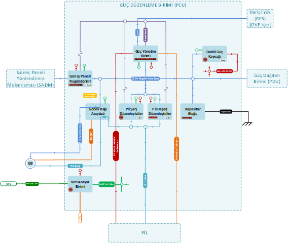
Power Conditioning Unit manages main bus regulation and battery charging autonomously with the help of 6 hot redundant battery discharge regulators, 2 cold redundant battery charge regulators, 6 solar array regulators and power management unit. The power needs of the electronics circuits inside the equipment are provided by auxilary power supply unit. The TM7TC communication of the PCU 100V is managed by MIL-STD-1553B and discrete data lines. In order to decrease main bus impedance and improve bus regulations, The PCU 100V utilizes capacitor bank. The PCU 100 V have interface to power EGSE to provide battery charging and energizing the satellite during AIT operations. The modules of the PCU is conected via a backplane board. There is also a busbar structure to carry high currents and voltages on main power bus.
Performance
- Power output
10kW (Sunlight)
9 kW (Eclipse) - Bus voltage 100±1 V
- Efficiency : >95,9 %
- Battery type: Li-Ion
- Battery charge current: 10 A (maximum)
- Battery management Autonomous
PDU
(Power Distribution Unit)
PDU 28V - İMECE
Power Distribution Unit 28V
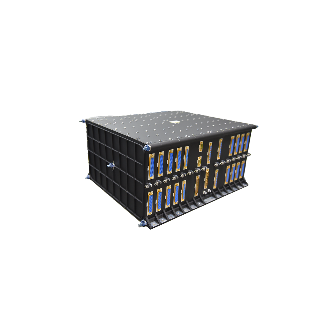
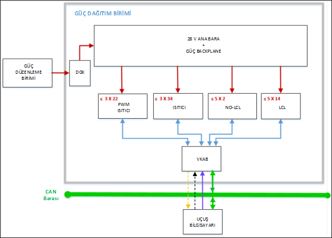
The Power Distribution Unit 28V (PDU 28V) is designed by TÜBİTAK UZAY for TÜRKSAT 6A Satellite in a fault tolerant and space qualified manner. The Power Distribution Unit (PDU) is a single integrated and modular unit to supply power to your payloads and platform unit of satellite up to 2 kW. The equipment operates under unregulated bus 28± 5V . It is the equipment responsible for the distribution, monitoring, and prevention of error propagation of the power needed to the satellite payloads and other platform equipment under all foreseen conditions and mission phases. PDU protects the satellite loads and prevent overload of the main power bus against excessive currents and enables each load to be switched by only Latching Current Limiter (LCL). The internal architecture of equipment is designed to comply with the reliability target with a single unit per spacecraft.
Key Features
- ESCC and MIL approved parts, materials and manufacturer preference in equipment design
- Latching current limiters design with enhanced stability and adjustable rapid reaction time
- Different current protection class LCL’s (1 A to 16 A) can be achieved
- Provide to the OBC TM for each load (voltage, current, status) necessary for satellite operation management
- PWM controlled heaters (LCL protected) provide high sensitivity temperature regulation
- The PDU can be directly plugged to Power Conditioning Unit (PCU) from one side and payload & platform from the other side, without any additional interface
Budget
Mass: 20 ±0.5 kg @ 2 kW
Volume: 368 x 428 x 240 mm3 @ 2.4 kW
Power: Up to 2 kW (at unregulated 28V bus bar)
Interfaces
Unregulated Power Bus, 28± 5V
TM/TC interface: CAN Bus and RS42
Power Outputs: Independent Commandable LCL Lines
Environmental Conditions
- Thermal: -25°C to +50°C
- Radiation: compatible to LEO ( 5 years mission lifetime)
- EMI/EMC: MIL-STD-461
- Vibrations: 20 g sine, 10 grms in Z plane and 7grms in X-Y plane random
- Shock: 40 to 1,200 g (0.1 to 10 kHz)
Use in Power Subsystem Scope
The Power Distribution Unit contains five Power Distribution Units (PDU) which are designed to have a maximum of 16 LCL’s, taking into account the number and power requirements of different loads. There are three Heater Distribution Units (HDU) that provide the power to the heaters on the satellite. There are eight heater groups in each unit that contains seven separate heater switches in series with LCL. The Data Interface Unit provides telemetry/ tele command interface between power and heater distribution units and the OBC. It communicates with the OBC via the CAN bus and RS422. PDU also has Auxiliary power supply (APS) to maintain its operation and has an opportunity to give external 5V to satellite units .
Performance
- Power output: 2 kW
- Bus Voltage: 28 ±5 V unregulated
- Efficiency: 98.5 % (Under Full Load of Operation)
- LCL Classes:
LCL (0.5 A, 1 A, 2 A, 3 A, 4 A, 5 A, 6 A, 7 A, 8 A, 9 A, 10 A and 16 A)
Normally-ON LCL (0.5 A, 1 A, 2 A and 3 A)
Heater LCL (0.5 A, 1 A, 2 A, 3 A, 4 A, 5 A and 6 A) - Number of power outputs: Up to 80 distribution lines, Up to 168 heater (66 PWM heaters)
PDU 100V - TÜRKSAT 6A
Power Distribution Unit 100V
Error-tolerant Power Distribution Unit 100V was developed and qualified to comply with space enviroments by TÜBİTAK UZAY in the frame of the communication satellite (TÜRKSAT-6A) for GEO satellites. It is the equipment responsible for the distribution, monitoring, and prevention of error propagation of the power needed to the satellite payloads and other platform equipment under all foreseen conditions and mission phases. PDU protects the satellite loads and prevent overload of the main power bus against excessive currents by Latching Current Limiter (LCL) and fuses.
Key Features
- Input Voltage : 100 ± 1V
- Output voltages : 100V, 50V
- Switchable Heater Lines (100V) :
56 number ~250W each
118 number ~100W each - Switchable Equipment Lines (100V) :
6 number ~100W each
2 number ~1,800W each
2 number ~250W each - Fuse Lines (100V) :
23 number ~600W each
26 number ~300W each
47 number ~180W each - Fuse Lines (50V) : 2 number ~30W each
- Efficiency while distributing : >98.8%
Mechanical Features
Mass: 26.5 ± 0.5 kg
Volume: 528 mm x 428 mm x 240 mm (W x H x L)
Interfaces
Bus bar: 100±1 V
Data line: MIL 1553
Environmental Conditions
- Thermal: -25°C to +55°C
- Radiation: compatible to GEO ( 15 years mission lifetime)
- EMI/EMC: MIL-STD-461
- Vibration/Shock: ECSS-E-ST-10-03
Use in Power Subsystem Scope
The power from PCU supplies the internal bus bar via capacitor bank in PDU, so the regulated 100V is distributed to another units. PDU's backplane is utilized to provide communication between each units by distributing low level signal. Besides, the backplane distributes auxiliary voltage to another units. PDU has two types of power distribution accoding to characteristic of the loads: LCL and fuse lines. The loads, which has to be switchable by PDU, are powered and protected via LCL. The PDU provides the fuses lines for essential loads which are not switchable by PDU. PDU also provides 2 number of 50V fuse lines with capability of 30 W. PDU can monitor current, voltage and status data and send the data to a SMU via MIL 1553.
Performance
- Power output: 10 kW
- Bar voltage: 100 ±1 V
- Efficiency: 98.8% (full load)
- Fuse types:
100 V (1 A, 3 A and 5 A)
50 V (0.6 A) - LCL Classes:
LCL (0.5 A, 5 A, 20 A)
Heater LCL (0.5 A, 1 A, 2 A, 3 A, 4 A, 5 A and 6 A) - Power output number: 166 number of fuse lines (100V), 224 number of heater lines ısıtıcı, 16 number of LCL lines, 2 number of fuse lines (50V)